Copyright © 2018 by Andrew Reid - BendTrack · All Rights reserved · E-Mail: andrew@bendtrack.com
The Home of BendTrack
The BendTrack Manual -- Adaptor Modules
Your Business Website
Your Company Slogan Here ...
Designed & Hosted by JunctionDesign
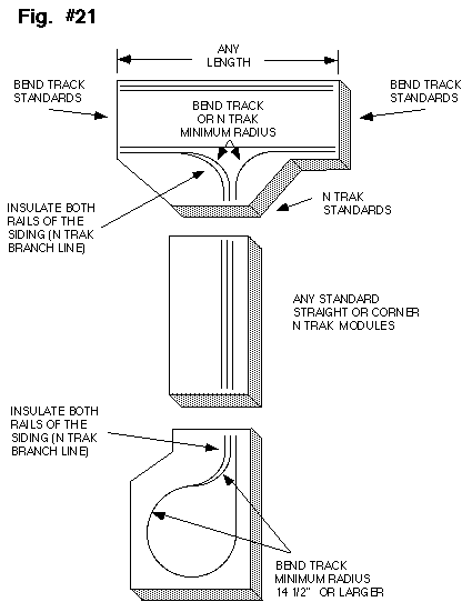
The second adapter is well suited to a club who has mostly BendTrack modules but would also like to include N-Trak in the layout. It consists of a "T" and a balloon module. They are designed so that any number of N-Trak modules can be connected between them. This adapter can't provide for a separate continuous run on N-Trak's branch line but does allow it to be used as a large switching lead for industries on the modules or as a large passing siding for BendTrack's mainline 1.
The "T" has the two wings laid to BendTrack standards and the shank to N-Trak standards. The balloon has it's connecting end laid to N-Trak standards. Straights, outside corners, and inside corners can be connected between the N-Trak interfaces of the two adapter modules. You'll see in the illustration that mainline 1 and 2 of the N-Trak modules are being used as an extension of Bend Track's mainline 1.
The "T" has the two wings laid to BendTrack standards and the shank to N-Trak standards. The balloon has it's connecting end laid to N-Trak standards. Straights, outside corners, and inside corners can be connected between the N-Trak interfaces of the two adapter modules. You'll see in the illustration that mainline 1 and 2 of the N-Trak modules are being used as an extension of Bend Track's mainline 1.
Combining BendTrack and N-Trak
Bend Track to N-Trak Adaptor
Also take note that on the short pieces of what would be N-Trak's branch line on the two adapter modules, there need to be insulators on both rails of the track before this branch line track merges with the mainline track. This will allow the branch line track of all the N-Trak modules between the "T" and balloon to be kept electrically isolated from BendTrack's mainline 1. This way whole trains on main 1 can pass each other and local switch engines can run on the branch line without having to use mainline power.
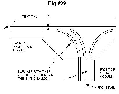
This adapter is the only one of the three that has some modifications to the standard wiring practices of either BendTrack or N-Trak. If you start at point A in figure #22 and move up and around in the diagram until you come to point B, you will see that the rail considered to be the "front" rail in an N-Trak module becomes the "rear" rail in a BendTrack module. This is a problem because the wiring specifications of both modular systems require that the "front" rail of the track be connected to the wide pin of the Cinch-Jones plugs. If the plugs at the N-Trak end of the "T" are wired the way it would at first seem they should be, with the front rail connected to the wide pin, there will be a direct short from the front rail to the rear rail on BendTrack main 1 when an N-Trak module is plugged in. The same thing would happen when the adapter balloon is plugged in. The solution to this is to flip the polarity of the Cinch-Jones plugs for the yellow and blue plugs of the "T" and balloon which means the ribbed wire of the zip cords connect to the narrow pin instead of the wide pin. This allows a standard N-Trak module (or modules) to operate with the yellow and blue track's polarity reversed with no short circuits. The next illustration shows how the wiring on the "T" and balloon is done.
The Original "N"ovative Modular System

Home
The Manual
Whats New?
History
Tips & Tricks
Links
Photo Gallery
Clubs & Groups
Support Us
Contact Us
The second adapter is well suited to a club who has mostly BendTrack modules but would also like to include N-Trak in the layout. It consists of a "T" and a balloon module. They are designed so that any number of N-Trak modules can be connected between them. This adapter can't provide for a separate continuous run on N-Trak's branch line but does allow it to be used as a large switching lead for industries on the modules or as a large passing siding for BendTrack's mainline 1.
The "T" has the two wings laid to BendTrack standards and the shank to N-Trak standards. The balloon has it's connecting end laid to N-Trak standards. Straights, outside corners, and inside corners can be connected between the N-Trak interfaces of the two adapter modules. You'll see in the illustration that mainline 1 and 2 of the N-Trak modules are being used as an extension of Bend Track's mainline 1.
If the plugs at the N-Trak end of the "T" are wired the way it would at first seem they should be, with the front rail connected to the wide pin, there will be a direct short from the front rail to the rear rail on BendTrack main 1 when an N-Trak module is plugged in. The same thing would happen when the adapter balloon is plugged in. The solution to this is to flip the polarity of the Cinch-Jones plugs for the yellow and blue plugs of the "T" and balloon which means the ribbed wire of the zip cords connect to the narrow pin instead of the wide pin. This allows a standard N-Trak module (or modules) to operate with the yellow and blue track's polarity reversed with no short circuits. The next illustration shows how the wiring on the "T" and balloon is done.
This adapter is the only one of the three that has some modifications to the standard wiring practices of either BendTrack or N-Trak. If you start at point A in figure #22 and move up and around in the diagram until you come to point B, you will see that the rail considered to be the "front" rail in an N-Trak module becomes the "rear" rail in a BendTrack module. This is a problem because the wiring specifications of both modular systems require that the "front" rail of the track be connected to the wide pin of the Cinch-Jones plugs.
The Original "N"ovative
Modular System
Modular System

Copyright © 2018 by Andrew Reid - BendTrack
All Rights reserved
E-Mail: andrew@bendtrack.com
All Rights reserved
E-Mail: andrew@bendtrack.com


Click Logo to go to the Top of the Page
Combining BendTrack & N-Trak


